Description
🔗 Connect, Control, Conquer: The Ultimate 8-Channel Relay Powerhouse
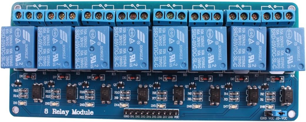
- HANDLE HEAVY LOADS - Robust relays rated for AC250V/10A and DC30V/10A empower you to control high-power devices confidently.
- AUTOMATE LIKE A PRO - Perfect for smart home setups and complex electronic projects, turning your ideas into reality with reliable switching.
- INSTANT VISUAL FEEDBACK - Built-in LED indicators provide real-time relay status, so you’re always in control and never in the dark.
- POWER UP WITH PRECISION - Efficient 5V operation with minimal 15-20mA current draw per channel keeps your projects sleek and energy-smart.
- PLUG PLAY COMPATIBILITY - Seamlessly integrates with Arduino, Raspberry Pi, and a wide range of microcontrollers for ultimate versatility.
The JBtek 8 Channel DC 5V Relay Module offers a high-current, low-power solution for controlling multiple appliances via microcontrollers like Arduino and Raspberry Pi. Featuring 10A relay capacity, LED status indicators, and broad compatibility, it’s designed for efficient, reliable automation in home and industrial projects.